Phase Shift Rectifier Transformer For High-Voltage Inverters
03-13 2025 | By:
Phase-shifting rectifier transformer is a natural companion for high-voltage inverters
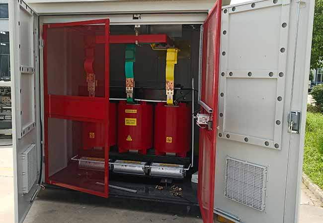
Dry phase-shift rectifier transformer is a device that specializes in providing multi-phase rectifier power for medium and high voltage inverters. It adopts the principle of phase shifting of the lengthwise triangle. Through multiple different phase shifting angle secondary windings, it can form a rectifier transformer with equivalent phase numbers of 9 phases, 12 phases, 18 phases and 27 phases. The primary side of the transformer directly enters the high-voltage power grid, and there are multiple three-phase windings on the secondary side of the transformer. It represents the extended triangular connection of each low-voltage three-phase winding on the secondary side of the transformer at 0°, θ°, …, (60-θ)°, etc., and also represents the phase shift angle of the line voltage of each low-voltage three-phase winding with respect to the third-class winding. When each phase is connected in series by n H-bridge units, θ=60°/n, multiplexing of inputs is achieved, forming a 6n pulse rectification. In this way, if the power of each H-bridge unit is balanced and the current amplitude is the same, theoretically, the input current on the network side does not contain harmonics below 6n±1, and the power factor can be improved. Generally, reactive compensation and harmonic filtering devices are no longer required. It is most suitable for use in environments with high fire protection requirements and large load fluctuations, such as offshore oil platforms, thermal power plants, water plants, metallurgy and chemical industry, mining and building materials, etc.
![]()
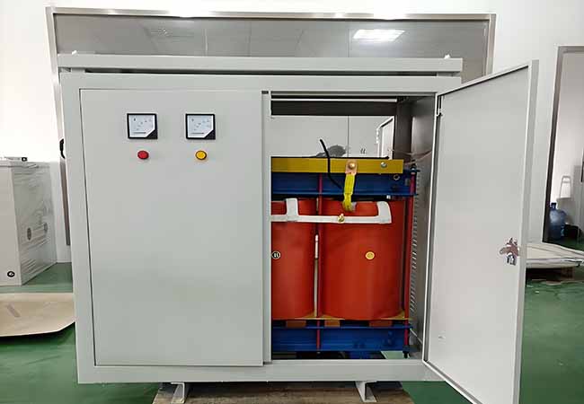
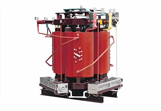
Frequency-converting phase shift rectifier transformer
2 Implementation standards
◇ICE726 “Dry Power Transformer”
◇GB6450~1986 “Dry Power Transformer”
◇GB/T10228~1977 “Technical Parameters and Requirements of Dry Power Transformers”
◇GB/T17211~1998 “Dry Power Transformer Load Guidelines”
◇GB/T10237~1998 “Insulation level and insulation test of power transformer”
◇GB4208~1993 “Shell Protection Level (IP Code)”
◇JB/T10008~1999《Sound level of 6~220KV transformer”
◇JB/T56009~1998 “Dry-type power transformer product quality classification”
◇JB/T8636-1997 “Power Rheological Transformer”
◇JB/DQ2113-1984 “Rectifier Transformer for Electrochemical”
3 Performance Features
High mechanical strength, strong short-circuit resistance, safe and reliable operation;
Low noise, small size, easy installation and maintenance-free;
High insulation level, small local discharge capacity, long product life;
It has strong resistance to moisture, heat shock and fire resistance;
Frequency-converting phase shift rectifier transformer Performance Parameters
| Type | Ratedcapacity(kVA) | Qtyof secwindings | Shortcircuit impedance(%) | Dimension (L×WxH,mm) | Totalweight(kg) |
| ZT(P)SFG(H)-250/6 | 250 | 9 12 15 18 21 | 6-9% | 1300×880×1440 | 970 |
| ZT(P)SFG(H)-315/6 | 315 | 1300×880×1440 | 1110 | ||
| ZT(P)SFG(H)-400/6 | 400 | 1360×880×1450 | 1200 | ||
| ZT(P)SFG(H)-500/6 | 500 | 1360×960×1490 | 1380 | ||
| ZT(P)SFG(H)-630/6 | 630 | 1360×960×1500 | 1530 | ||
| ZT(P)SFG(H)-710/6 | 710 | 1440×960×1500 | 1680 | ||
| ZT(P)SFG(H)-800/6 | 800 | 1480×960×1520 | 1790 | ||
| ZT(P)SFG(H)-900/6 | 900 | 1480×960×1540 | 1940 | ||
| ZT(P)SFG(H)-1000/6 | 1000 | 1500×960×1550 | 2110 | ||
| ZT(P)SFG(H)-1120/6 | 1120 | 1550×960×1580 | 2190 | ||
| ZT(P)SFG(H)-1250/6 | 1250 | 1580×960×1630 | 2440 | ||
| ZT(P)SFG(H)-1400/6 | 1400 | 1610×1020×1630 | 2610 | ||
| ZT(P)SFG(H)-1600/6 | 1600 | 1660×1020×1680 | 2890 | ||
| ZT(P)SFG(H)-1800/6 | 1800 | 1650×1020×1740 | 3060 | ||
| ZT(P)SFG(H)-2000/6 | 2000 | 1680×1020×1800 | 3420 | ||
| ZT(P)SFG(H)-2250/6 | 2250 | 1720×1020×1840 | 3810 | ||
| ZT(P)SFG(H)-2500/6 | 2500 | 1760×1020×1860 | 4120 | ||
| ZT(P)SFG(H)-2800/6 | 2800 | 1800×1020×1860 | 4490 | ||
| ZT(P)SFG(H)-3000/6 | 3000 | 1820×1120×1860 | 4840 | ||
| ZT(P)SFG(H)-3150/6 | 3150 | 1860×1120×1900 | 5200 | ||
| ZT(P)SFG(H)-3500/6 | 3500 | 1900×1120×1940 | 5620 | ||
| ZT(P)SFG(H)-3750/6 | 3750 | 1960×1120×2050 | 5810 | ||
| ZT(P)SFG(H)-4000/6 | 4000 | 1990×1200×2050 | 6210 | ||
| ZT(P)SFG(H)-4500/6 | 4500 | 2070×1200×2100 | 6910 | ||
| ZT(P)SFG(H)-5000/6 | 5000 | 2150×1200×2100 | 7440 | ||
| ZT(P)SFG(H)-6300/6 | 6300 | 2200×1300×2140 | 8860 | ||
| ZT(P)SFG(H)-8000/6 | 8000 | 2200×1300×2200 | 9670 |
| Type | Ratedcapacity(kVA) | Qtyof secwindings | Shortcircuit impedance(% ) | Dimension(LxWxH,mm ) | Total weight(kg) |
| ZT(P)SFG(H)-315/10 | 315 | 15 18 21 24 27 30 36 | 6-9% | 1380×920×1450 | 1090 |
| ZT(P)SFG(H)-400/10 | 400 | 1380×920×1490 | 1250 | ||
| ZT(P)SFG(H)-500/10 | 500 | 1420×960×1520 | 1410 | ||
| ZT(P)SFG(H)-630/10 | 630 | 1450×960×1550 | 1640 | ||
| ZT(P)SFG(H)-710/10 | 710 | 1480×960×1580 | 1780 | ||
| ZT(P)SFG(H)-800/10 | 800 | 1530×960×1620 | 1860 | ||
| ZT(P)SFG(H)-900/10 | 900 | 1580×960×1640 | 2050 | ||
| ZT(P)SFG(H)-1000/10 | 1000 | 1640×960×1660 | 2250 | ||
| ZT(P)SFG(H)-1120/10 | 1120 | 1640×1020×1680 | 2300 | ||
| ZT(P)SFG(H)-1250/10 | 1250 | 1680×1020×1720 | 2470 | ||
| ZT(P)SFG(H)-1400/10 | 1400 | 1700×1020×1760 | 2810 | ||
| ZT(P)SFG(H)-1600/10 | 1600 | 1780x1020x1800 | 3040 | ||
| ZT(P)SFG(H)-1800/10 | 1800 | 1780×1020×1820 | 3360 | ||
| ZT(P)SFG(H)-2000/10 | 2000 | 1780×1020×1860 | 3690 | ||
| ZT(P)SFG(H)-2250/10 | 2250 | 1780×1020×1900 | 4170 | ||
| ZT(P)SFG(H)-2500/10 | 2500 | 1800×1020×1900 | 4410 | ||
| ZT(P)SFG(H)-2800/10 | 2800 | 1840×1120×1950 | 4720 | ||
| ZT(P)SFG(H)-3000/10 | 3000 | 1880×1120×1950 | 5020 | ||
| ZT(P)SFG(H)-3150/10 | 3150 | 1920×1120×2000 | 5400 | ||
| ZT(P)SFG(H)-3500/10 | 3500 | 1980×1120×2050 | 5400 | ||
| ZT(P)SFG(H)-3750/10 | 3750 | 2010×1200×2050 | 5900 | ||
| ZT(P)SFG(H)-4000/10 | 4000 | 2060×1200×2080 | 6360 | ||
| ZT(P)SFG(H)-4500/10 | 4500 | 2120×1200×2100 | 6960 | ||
| ZT(P)SFG(H)-5000/10 | 5000 | 2200×1200×2150 | 7440 | ||
| ZT(P)SFG(H)-6300/10 | 6300 | 2250×1300×2150 | 8950 | ||
| ZT(P)SFG(H)-8000/10 | 8000 | 2250×1350×2250 | 10900 |
You may also find these interesting: