Phase-Shifting Rectifier Transformer – An Important Supporting Role In High-Voltage Frequency Converters
03-13 2025 | By:
High-voltage frequency conversion speed regulation technology has developed rapidly in recent years. In today’s world of energy shortage and increasingly serious environmental problems, energy conservation and emission reduction have already had quantitative assessment indicators. The speed regulation mode of medium-voltage motors has been changed to frequency conversion speed regulation, which has been promoted as a general energy-saving technology in the “Eleventh Five-Year Plan”. The relationship between the motor speed n and the power supply frequency f, slip rate s, and motor pole pair number p is n=60f(1-s)/p. Since there is a linear relationship between n and f, this speed regulation has the characteristics of stepless and wide range, and there is no power loss caused by excitation slip and throttling during the speed regulation process. According to statistics, the power saving effect can reach more than 30% through frequency conversion speed regulation.
![]()
2 H-class dry-type rectifier transformer is more suitable for high-voltage inverter
Due to the current diversity of the topological structure of high-voltage inverters, the cascade multiplexing technology represented by Siemens (formerly Asirobicon) technology can basically achieve perfect harmonic-free. It uses a rectifier transformer to superimpose (connect in series) multiple low-voltage modules to form a high-voltage output. The power device uses IGBT. At present, most domestic high-voltage inverter manufacturers use this technology, including Toshiba, Mitsubishi, Hitachi, etc. ABB’s ACS5000 series inverter is a three-level topological structure. The 36-pulse rectifier transformer has a total of 6 phase shift groups. Every 2 phase shift groups supply power to a frequency conversion unit. The power device is IGCT. ABB also has an inverter that uses 12-pulse rectifier inverter technology, and its transformer uses a three-winding form. The 18-pulse rectifier inverter technology represented by AB (Rockwell) is different from Asirobicon and ABB. It requires the rectifier transformer to adopt a three-split form.
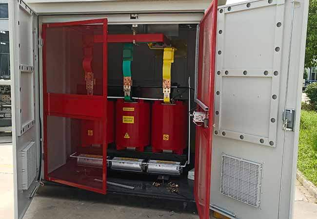
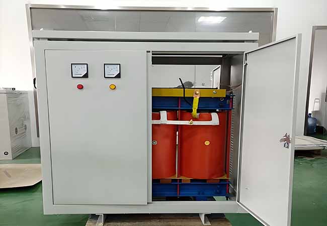
The high-voltage inverter is a complete set of equipment, which consists of a transformer unit cabinet, a power unit cabinet, a control unit cabinet, and some are equipped with a bypass cabinet, etc. Since the rectifier transformer is placed in the cabinet, the transformer needs to have a high heat resistance level, good heat dissipation, and strong overload capacity.
The temperature resistance level of the H-class dry-type rectifier transformer is 180℃, and the main insulating material is Nomex paper, which is a patented product of DuPont in the United States. It is a synthetic insulating material based on aromatic amide fiber, which is C-class and has a temperature resistance of 220℃. Nomex paper has many advantages. It is an excellent electrical insulation material. The transformer made of it can be moisture-proof, flame-retardant, and has good environmental adaptability. In addition, the transformer is compact in size and occupies little space. The transformer’s resistance to cold and heat shock, short circuit resistance, and overvoltage resistance are better than other types of transformers. In particular, the manufacturing process and product structure characteristics of the H-class rectifier transformer have very obvious advantages for rectifier transformers that require multiple taps and complex structures with multiple phase-shifting windings, making their manufacturing and processing cycle short, cost low, and the winding rigidity and mechanical strength guaranteed after vacuum pressure impregnation (VIP). At the same time, due to the paint film covering the surface of the insulating material, the moisture resistance of the transformer is improved.
Phase-Shifting Rectifier Transformer Performance Parameters
| Type | Ratedcapacity(kVA) | Qtyof secwindings | Shortcircuit impedance(%) | Dimension (L×WxH,mm) | Totalweight(kg) |
| ZT(P)SFG(H)-250/6 | 250 | 9 12 15 18 21 | 6-9% | 1300×880×1440 | 970 |
| ZT(P)SFG(H)-315/6 | 315 | 1300×880×1440 | 1110 | ||
| ZT(P)SFG(H)-400/6 | 400 | 1360×880×1450 | 1200 | ||
| ZT(P)SFG(H)-500/6 | 500 | 1360×960×1490 | 1380 | ||
| ZT(P)SFG(H)-630/6 | 630 | 1360×960×1500 | 1530 | ||
| ZT(P)SFG(H)-710/6 | 710 | 1440×960×1500 | 1680 | ||
| ZT(P)SFG(H)-800/6 | 800 | 1480×960×1520 | 1790 | ||
| ZT(P)SFG(H)-900/6 | 900 | 1480×960×1540 | 1940 | ||
| ZT(P)SFG(H)-1000/6 | 1000 | 1500×960×1550 | 2110 | ||
| ZT(P)SFG(H)-1120/6 | 1120 | 1550×960×1580 | 2190 | ||
| ZT(P)SFG(H)-1250/6 | 1250 | 1580×960×1630 | 2440 | ||
| ZT(P)SFG(H)-1400/6 | 1400 | 1610×1020×1630 | 2610 | ||
| ZT(P)SFG(H)-1600/6 | 1600 | 1660×1020×1680 | 2890 | ||
| ZT(P)SFG(H)-1800/6 | 1800 | 1650×1020×1740 | 3060 | ||
| ZT(P)SFG(H)-2000/6 | 2000 | 1680×1020×1800 | 3420 | ||
| ZT(P)SFG(H)-2250/6 | 2250 | 1720×1020×1840 | 3810 | ||
| ZT(P)SFG(H)-2500/6 | 2500 | 1760×1020×1860 | 4120 | ||
| ZT(P)SFG(H)-2800/6 | 2800 | 1800×1020×1860 | 4490 | ||
| ZT(P)SFG(H)-3000/6 | 3000 | 1820×1120×1860 | 4840 | ||
| ZT(P)SFG(H)-3150/6 | 3150 | 1860×1120×1900 | 5200 | ||
| ZT(P)SFG(H)-3500/6 | 3500 | 1900×1120×1940 | 5620 | ||
| ZT(P)SFG(H)-3750/6 | 3750 | 1960×1120×2050 | 5810 | ||
| ZT(P)SFG(H)-4000/6 | 4000 | 1990×1200×2050 | 6210 | ||
| ZT(P)SFG(H)-4500/6 | 4500 | 2070×1200×2100 | 6910 | ||
| ZT(P)SFG(H)-5000/6 | 5000 | 2150×1200×2100 | 7440 | ||
| ZT(P)SFG(H)-6300/6 | 6300 | 2200×1300×2140 | 8860 | ||
| ZT(P)SFG(H)-8000/6 | 8000 | 2200×1300×2200 | 9670 |
| Type | Ratedcapacity(kVA) | Qtyof secwindings | Shortcircuit impedance(% ) | Dimension(LxWxH,mm ) | Total weight(kg) |
| ZT(P)SFG(H)-315/10 | 315 | 15 18 21 24 27 30 36 | 6-9% | 1380×920×1450 | 1090 |
| ZT(P)SFG(H)-400/10 | 400 | 1380×920×1490 | 1250 | ||
| ZT(P)SFG(H)-500/10 | 500 | 1420×960×1520 | 1410 | ||
| ZT(P)SFG(H)-630/10 | 630 | 1450×960×1550 | 1640 | ||
| ZT(P)SFG(H)-710/10 | 710 | 1480×960×1580 | 1780 | ||
| ZT(P)SFG(H)-800/10 | 800 | 1530×960×1620 | 1860 | ||
| ZT(P)SFG(H)-900/10 | 900 | 1580×960×1640 | 2050 | ||
| ZT(P)SFG(H)-1000/10 | 1000 | 1640×960×1660 | 2250 | ||
| ZT(P)SFG(H)-1120/10 | 1120 | 1640×1020×1680 | 2300 | ||
| ZT(P)SFG(H)-1250/10 | 1250 | 1680×1020×1720 | 2470 | ||
| ZT(P)SFG(H)-1400/10 | 1400 | 1700×1020×1760 | 2810 | ||
| ZT(P)SFG(H)-1600/10 | 1600 | 1780x1020x1800 | 3040 | ||
| ZT(P)SFG(H)-1800/10 | 1800 | 1780×1020×1820 | 3360 | ||
| ZT(P)SFG(H)-2000/10 | 2000 | 1780×1020×1860 | 3690 | ||
| ZT(P)SFG(H)-2250/10 | 2250 | 1780×1020×1900 | 4170 | ||
| ZT(P)SFG(H)-2500/10 | 2500 | 1800×1020×1900 | 4410 | ||
| ZT(P)SFG(H)-2800/10 | 2800 | 1840×1120×1950 | 4720 | ||
| ZT(P)SFG(H)-3000/10 | 3000 | 1880×1120×1950 | 5020 | ||
| ZT(P)SFG(H)-3150/10 | 3150 | 1920×1120×2000 | 5400 | ||
| ZT(P)SFG(H)-3500/10 | 3500 | 1980×1120×2050 | 5400 | ||
| ZT(P)SFG(H)-3750/10 | 3750 | 2010×1200×2050 | 5900 | ||
| ZT(P)SFG(H)-4000/10 | 4000 | 2060×1200×2080 | 6360 | ||
| ZT(P)SFG(H)-4500/10 | 4500 | 2120×1200×2100 | 6960 | ||
| ZT(P)SFG(H)-5000/10 | 5000 | 2200×1200×2150 | 7440 | ||
| ZT(P)SFG(H)-6300/10 | 6300 | 2250×1300×2150 | 8950 | ||
| ZT(P)SFG(H)-8000/10 | 8000 | 2250×1350×2250 | 10900 |
3 Multiplexing technology is realized through transformers
The perfect harmonic-free inverter uses multiple phase-shifting groups of the rectifier transformer to form a phase difference between each secondary winding. Each phase-shifting group supplies power to the corresponding power unit, realizing the input multiplexing effect, completing rectification, inversion, and frequency conversion in these units, and then superimposing them. With multiple phase shifting, the pollution of the harmonics generated by each unit to the power grid can be eliminated. This is the basic working principle of the perfect harmonic-free inverter. As an important supporting role of this technology, the rectifier transformer has developed rapidly with the emergence of high-voltage inverters. According to the number of inverter units and voltage levels, the number of output windings and voltage of the phase-shifting rectifier transformer are also different. 3kv mostly adopts 3 levels, the phase shift is divided into 0° and ±20°, and the voltage of each phase shift group is 630v; 6kv mostly adopts 6 levels, the phase shift is divided into ±5°, ±15°, ±25°, and the voltage of each phase shift group is 630v; there are also 5 or 7 levels, the phase shift angle is 0°, ±12°, ±24° at level 5, and the voltage is 710v; the phase shift angle is 0°, ±8.57°, ±17.14°, ±25.71° at level 7, and the voltage is 490v; 10kv mostly adopts 8 levels, the phase shift is divided into ±3.75°, ±11.25°, ±18.75°, ±26.25°, and the voltage of each phase shift group is 720v, and there are also 9 and 10 levels.
Theoretically, the more stages there are, the fewer harmonics there are on the input side of the transformer, and the less pollution there is to the power grid. However, the more stages there are, the more power units there are in the high-voltage inverter, which increases the manufacturing cost. Therefore, the above stages are generally adopted by inverter manufacturers. The transformer required for ABB’s ACS5000 inverter is simpler in structure than the above ones; 12-pulse and 18-pulse rectifier transformers mostly adopt a split method, which is suitable for ABB and AB’s high-voltage inverters.
4 Differences in the structure of rectifier transformers among inverter manufacturers
Due to the differences in technology and installation methods among inverter manufacturers, there are significant differences in the structure of rectifier transformers, which are as follows:
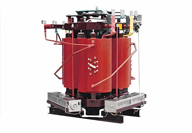
(1) Rectifier transformers represented by Siemens (formerly Asirobicon) adopt two structural forms. Small capacity adopts a vertical structure, which has a compact transformer design, small footprint, good processability, high mechanical strength, good heat dissipation, and strong overload capacity. Large capacity adopts a conventional horizontal structure, which is easy to manufacture and install.
(2) The rectifier transformer of Beijing Lidehuafu Electric Technology Co., Ltd. adopts a conventional horizontal structure. There is a centralized terminal board, which is arranged on the left or right side of the transformer for easy wiring. Each phase shifting group adopts a triangular phase shifting along the edge, and the corner sealing wire uses NZB paper-wrapped electromagnetic wire.
(3) Several inverter manufacturers represented by Guangdong Mingyang Longyuan Power Electronics Co., Ltd. and Hubei Sanhuan Development Co., Ltd. are basically similar to the rectifier transformer of Beijing Lidehuafu Electric Technology Co., Ltd. in transformer structure, except that a windshield is added to the transformer.
(4) The corner sealing wire of the transformer phase shifting group of Oriental Hitachi (Chengdu) Electric Control Equipment Co., Ltd. uses a cable with a high temperature resistance of 150℃ and a voltage resistance of 7500V, and the windshield is set at the upper third.
(5) The transformer of Toshiba Corporation of Japan requires a square coil structure to reduce the width direction size, and a small wheel is configured at the bottom to facilitate on-site installation and movement. The wiring terminals of each phase shifting group are concentrated on the left or right side of the transformer.
(6) 12-pulse and 18-pulse rectifier transformers for ABB and AB.
(7) Requirements for rectifier transformer accessories
Generally, the requirements for rectifier transformer accessories are to be equipped with fans and thermostats. The temperature sensor is mostly a PT100 probe, which is buried in the hottest point of the transformer. The temperature signal is transmitted to the thermostat or temperature control box through it. The thermostat displays the temperature in three phases. The thermostat sets three control points, which respectively start the fan, over-temperature alarm, and over-temperature trip function. Some manufacturers require the burial of a temperature switch with a normally closed contact, which directly provides a temperature signal to control the operation and stop of the inverter. 12-pulse and 18-pulse transformers basically have casings with different protection levels and can be placed separately from the inverter.
5 Process of rectifier transformer serialization
According to the power and voltage level of the medium-voltage motor, the rectifier transformers required by the inverter have been gradually serialized. As a new series of products, there is no targeted performance standard at present. The transformer industry has a professional standard for converter transformers, jb/t8636-1997, and the national standard for dry-type transformers, gb6450-1999, can be adopted as part of the general standard. Each inverter manufacturer has a set of specific technical requirements to guide the production and design of transformers. At present, the development trend of this type of product is to single large capacity such as more than 6000kva, different use occasions such as high altitude, hot and humid areas, offshore platforms, and countries with a power supply frequency of 60hz.
6 The market concentration of rectifier transformers is relatively high
Since medium-voltage motors are important controlled objects, the variable frequency speed regulation system is required to be quite reliable, which also puts forward high requirements on the reliability of rectifier transformers. When inverter manufacturers choose transformer matching manufacturers, they first look at the performance and then the hardware. This type of transformer has many differences from ordinary transformers in electromagnetic calculation and structural design. Compared with other rectifier transformers, there are also many special features, such as how to ensure that the hot spot temperature rise of the transformer meets the requirements of the insulation level under the condition of multiple harmonic content; how to reduce harmonic current by calculating the secondary impedance; how to arrange the seemingly complicated secondary outlets in an orderly manner during the manufacturing process to ensure the insulation level of each part, etc., are all important issues that need to be seriously addressed. Therefore, the entry threshold for the production of rectifier transformers is relatively high. At present, the domestic market is mainly concentrated in 3~4 transformer manufacturers. Among them, ztelecgroup. entered this field early, with mature technology, relatively stable quality, and rapid production capacity improvement. The market share is close to 60%, and the annual production of various rectifier transformers reaches 600~800 units. There are more than a dozen high-voltage inverter companies supporting it. The maximum capacity of a single unit has reached 7000kva, and the power frequency can also reach 60hz. The voltage level covers all levels of medium voltage below 10kv, and it is matched with the inverter connected to the motor outlet voltage of 13.8kv. ztelecgroup has independent intellectual property rights in the research and development and production of such products, and owns multiple patent technologies.
7 Conclusion
The phase-shifting rectifier transformer is matched with the high-tech energy-saving product – high-voltage inverter, which makes it also have the concept of high technology and has a good development prospect. In addition, since there are not many technicians engaged in such products, there are still many topics in the design and calculation of products that need further theoretical research, such as leakage magnetic field, temperature field, harmonic content, secondary impedance, cooling and heat dissipation methods of larger capacity products, multiple phase shifting methods, and multiple structural forms. These are all important issues that need to be solved as soon as possible in the near future. Through hard work, our company will definitely hand in an excellent answer.
You may also find these interesting: