10kV Distribution Transformer Basic Knowledge
04-14 2025 | By:
Distribution transformer, referred to as “distribution transformer“. Refers to a static electrical appliance in the power distribution system that transforms AC voltage and current according to the law of electromagnetic induction to transmit AC power. Distribution transformers usually refer to power transformers that operate in the distribution network with a voltage level of 10-35kV (mostly 10kV and below) and a capacity of 6300KVA and below to directly supply power to end users.
1. Basic introduction to power distribution
1.1 Definition
Distribution transformer, referred to as “distribution transformer”, refers to a static electrical appliance in the power distribution system that transforms AC voltage and current according to the law of electromagnetic induction to transmit AC power. In some areas, power transformers with voltage levels below 35 kV (mostly 10KV and below) are called “distribution transformers”, referred to as “distribution transformers”. The place and place where “distribution transformers” are installed is the substation. Distribution transformers should be installed on poles or on the ground in the open air.
1.2 Structure
This time, the editor introduces the structure of oil-immersed distribution transformers. Oil-immersed distribution transformers can be divided into body, oil storage cabinet, insulating bushing, tap changer, protection device, etc. according to their structure.
1.2.1 Body
The body consists of three parts: core, winding and insulating oil. The winding is the circuit of the transformer, and the core is the magnetic circuit of the transformer. The two constitute the core of the transformer, that is, the electromagnetic part.
1.2.1.1 Core
The core is the main magnetic circuit part of the transformer. It is usually made of hot-rolled or cold-rolled silicon steel sheets with a high silicon content, a thickness of 0.35 or 0.5mm, and an insulating paint on the surface. The core is divided into two parts: the core column and the iron yoke. The core column is covered with windings, and the iron yoke is used to close the magnetic circuit. The basic forms of the core structure are core type and shell type
1.2.1.2 Winding
The winding is the circuit part of the transformer, which is generally wound on a winding die with insulated flat copper wire or round copper wire. The winding is set on the transformer core column, the low-voltage winding is in the inner layer, and the high-voltage winding is set on the outer layer of the low-voltage winding. The low-voltage winding and the core, and the high-voltage winding and the low-voltage winding are separated by sleeves made of insulating materials for insulation.
1.2.1.3 Insulating oil
The composition of transformer oil is very complex, mainly composed of cycloalkanes, alkanes and aromatic hydrocarbons. In the distribution transformer, transformer oil plays two roles: one is to insulate between transformer windings and windings, windings and cores and oil tanks. The second is that the transformer oil generates convection after being heated, which plays a heat dissipation role for the transformer core and windings. Commonly used transformer oils are No. 10, No. 25 and No. 45. The number indicates the temperature at which the oil begins to solidify below zero. For example, “No. 25” oil means that this oil begins to solidify at minus 25℃. The oil specification should be selected according to local climatic conditions.
1.2.2 Oil storage cabinet
The oil storage cabinet is installed on the top cover of the oil tank. The volume of the oil conservator is about 10% of the volume of the oil tank. There is a pipe connecting the oil conservator and the oil tank. When the volume of the transformer expands or shrinks with the temperature of the oil, the oil conservator plays the role of storing and replenishing oil to ensure that the core and winding are immersed in the oil; at the same time, due to the installation of the oil conservator, the contact surface between the oil and the air is reduced, and the deterioration rate of the oil is reduced.
There is an oil mark on the side of the oil conservator, and next to the glass tube there is an oil level standard line when the oil temperature is -30℃, +20℃ and +40℃, indicating the oil level that the transformer that has not been put into operation should reach; the standard line can mainly reflect whether the oil volume is sufficient when the transformer is running at different temperatures.
There is a breathing hole on the oil conservator to connect the upper space of the oil conservator to the atmosphere. When the transformer oil expands and contracts, the air on the upper part of the oil conservator can enter and exit through the breathing hole, and the oil level can rise or fall, preventing the oil tank from deformation or even damage.
1.2.3 Insulating bushing
It is the main insulating device outside the transformer box. Most transformer insulating bushings are made of porcelain insulating bushings. The transformer uses high and low voltage insulating bushings to lead the leads of the high and low voltage windings of the transformer from the oil tank to the outside of the oil tank, so that the transformer windings are insulated from the ground (shell and core), and it is also the main component for connecting the fixed leads to the external circuit. The high voltage porcelain bushing is relatively tall, and the low voltage porcelain bushing is relatively short.
1.2.4 Tap changer
The device for changing the tap of the high voltage winding of the transformer, adjusting the tap position, can increase or decrease the number of turns of the primary winding part to change the voltage ratio and adjust the output voltage. After the transformer is out of operation and disconnected from the power grid, the output voltage is adjusted by manually changing the position of the tap switch, which is called no-load voltage regulation.
1.2.5 Protection device
1.2.5.1 Gas relay
The gas relay is installed between the connecting pipe between the transformer oil tank and the oil storage cabinet, and is connected to the control circuit to form a gas protection device. The upper contact of the gas relay and the light gas signal form a separate circuit, and the lower contact of the gas relay is connected to the external circuit to form heavy gas protection. The heavy gas action causes the high-voltage circuit breaker to trip and send out a heavy gas action signal;
1.2.5.2 Explosion-proof tube
The explosion-proof tube is a safety protection device for the transformer. It is installed on the large cover of the transformer. The explosion-proof tube is connected to the atmosphere. When a fault occurs, the heat will vaporize the transformer oil, triggering the gas relay to send out an alarm signal or cut off the power supply to prevent the oil tank from bursting.
2. Classification
2.1 Classification by installation location
Distribution transformers are divided into indoor and outdoor according to the installation location.
Outdoor installation is divided into platform type, pole tower type and floor type (including pre-installed type).
2.1.1 Pole tower type
The pole tower type is to install the transformer on a frame on the pole. It is divided into single-pole type and double-pole type.
When the capacity of the distribution transformer is 30KVA or less (including 30KVA), a single-pole distribution transformer stand is generally used. The distribution transformer, high-voltage drop-out fuse and high-voltage lightning arrester are installed on a cement pole, and the pole body should be tilted 13°-15° in the opposite direction of the assembled distribution transformer.
When the capacity of the distribution transformer is 50KVA~315KVA, a double-pole distribution transformer platform is generally used. The distribution transformer platform consists of a main pole cement pole and another auxiliary auxiliary pole. The main pole is equipped with a high-voltage drop-out fuse and a high-voltage down conductor, and the auxiliary pole has a secondary reverse conductor. The double-pole distribution transformer platform is stronger than the single-pole distribution transformer.
Advantages of pole tower installation: less space, no need for walls or fences around, the live part is high from the ground, and accidents are not easy to occur. Disadvantages: The platform uses more steel and the cost is higher.
2.1.2 Platform pier type
The platform pier type is a 0.5-1m square pier built with bricks and stones under the transformer pole, and the transformer is placed on it. Generally, transformers above 315KVA are installed.
The following points should be noted when installing a pedestal transformer:
(1) A solid fence or wall with a height of not less than 1.8m should be installed around the transformer. The door should be locked and kept by a designated person.
(2) The fence or wall should be at a safe operating distance from the transformer.
(3) Warning signs such as “High voltage danger, no climbing” should be hung on the pole or wall to prevent people and animals from approaching.
Advantages of pedestal installation: low cost and easy maintenance and repair. Disadvantages: It occupies a large area and a fence must be installed around it. Small animals can easily climb onto the live parts, which can easily cause damage by external forces.
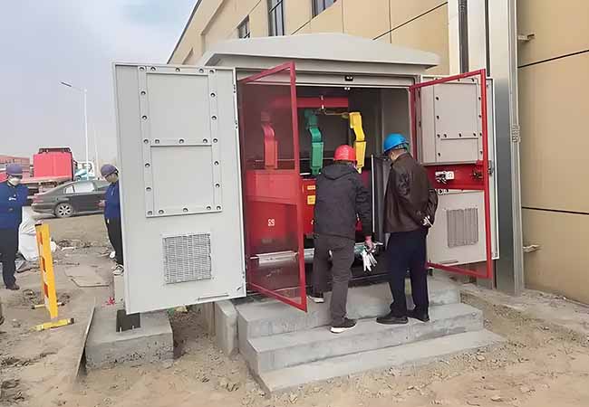
2.1.3 Floor-standing type
The floor-standing type means that the transformer is placed directly on the ground, and the high-voltage down conductor, drop-out fuse and lightning arrester are all on the line terminal pole.
The following points should be noted when installing a floor-standing transformer:
(1) A reliable fence must be installed around the transformer. The door should be locked and kept by a designated person.
(2) Warning signs such as “High voltage danger, no climbing” must be hung outside the fence.
(3) Because the live parts of the transformer are very low to the ground, the power supply must be cut off before entering the fence.
2.2 Classification by cooling method
According to the cooling method, it can be divided into oil-immersed and dry-type transformers.
Oil-immersed transformers rely on oil as a cooling medium, such as oil-immersed self-cooling, oil-immersed air cooling, oil-immersed water cooling, forced oil circulation, etc. Dry-type transformers rely on air convection for natural cooling or add fan cooling, and are mostly used for high-rise buildings, highway toll stations, local lighting, electronic circuits and other small-capacity transformers.
2.2.1 Oil-immersed transformers are divided into the following according to the shell type:
1) Non-enclosed oil-immersed transformers: mainly S8, S9, S10 and other series products, widely used in industrial and mining enterprises, agriculture and civil buildings.
2) Sealed oil-immersed transformers: mainly S9, S9-M, S10-M and other series of products, mostly used in places with oil and chemicals in the petroleum and chemical industries.
3) Sealed oil-immersed transformers: mainly BS9, S9- , S10- , S11-MR, SH, SH12-M and other series of products, can be used for power distribution in various places such as industrial and mining enterprises, agriculture, and civil buildings.
2.2.2 Dry-type transformers are divided into the following according to the insulating medium:
1) Encapsulated coil dry-type transformers: mainly SCB8, SC (B) 9, SC (B) 10, SCR-10 and other series of products, suitable for high-rise buildings, commercial centers, airports, stations, subways, hospitals, factories and other places.
2) Non-encapsulated coil dry-type transformers: mainly SG10 and other series of products, suitable for high-rise buildings, commercial centers, airports, stations, subways, petrochemicals and other places.
2.3 Classification of electric voltage regulation methods
According to the voltage regulation method, it can be divided into on-load voltage regulation and off-load voltage regulation.
The so-called off-load voltage regulation and on-load voltage regulation both refer to the voltage regulation method of the transformer tap changer. The difference is that the off-load voltage regulator does not have the ability to switch gears with load, and the transformer must be shut down when switching gears. The on-load tap changer can switch gears with load.
2.4 Classification of phases
According to the number of phases, it can be divided into single-phase transformers and three-phase transformers.
Single-phase transformer Single-phase transformer is a transformer with single-phase windings for both primary and secondary windings. Single-phase transformers have simple structure, small size, low loss, mainly small iron loss, and are suitable for application and promotion in low-voltage distribution networks with low load density.
Detailed graphic explanation of basic knowledge of 10kV distribution transformers
Three-phase transformers are used to increase and decrease voltage in three-phase systems. Three-phase transformers generally have three windings on the primary side, and their connection methods are divided into triangle, star, extended triangle, etc. The voltage phases on the three windings differ by 120 degrees, which is the common three-phase 380V connection method. The traditional iron core is three-phase three-core column, three-phase five-core column, involute shape, etc.
3. Working principle
The transformer consists of an iron core (or magnetic core) and a coil. The coil has two or more windings, of which the winding connected to the power supply is called the primary coil, and the remaining windings are called secondary coils. It can transform AC voltage, current and impedance. The simplest iron core transformer consists of an iron core made of soft magnetic material and two coils with different numbers of turns on the iron core
Transformer coil principle
The role of the iron core is to strengthen the magnetic coupling between the two coils. In order to reduce the eddy current and hysteresis loss in the iron, the iron core is made of painted silicon steel sheets; there is no electrical connection between the two coils, and the coils are wound with insulated copper wire (or aluminum wire). One coil connected to the AC power supply is called the primary coil (or primary coil), and the other coil connected to the electrical appliance is called the secondary coil (or secondary coil). The actual transformer is very complex, and it is inevitable that there are copper losses (heating of the coil resistance), iron losses (heating of the iron core) and leakage magnetic flux (magnetic induction lines closed by air), etc. In order to simplify the discussion, only the ideal transformer is introduced here. The conditions for the establishment of an ideal transformer are: ignoring the leakage magnetic flux, ignoring the resistance of the primary and secondary coils, ignoring the loss of the iron core, and ignoring the no-load current (the current in the primary coil when the secondary coil is open). For example, when the power transformer is running at full load (the secondary coil outputs the rated power), it is close to the ideal transformer situation.
The transformer is a static electrical appliance made using the principle of electromagnetic induction. When the primary coil of the transformer is connected to the AC power supply, an alternating magnetic flux is generated in the iron core, and the alternating magnetic flux is generally represented by φ. The φ in the primary and secondary coils is the same, and φ is also a simple harmonic function, expressed as φ=φmsinωt. According to Faraday’s law of electromagnetic induction, the induced electromotive force in the primary and secondary coils is e1=-N1dφ/dt, e2=-N2dφ/dt. In the formula, N1 and N2 are the turns of the primary and secondary coils. From the figure, we can see that U1=-e1, U2=e2 (the physical quantity of the primary coil is represented by subscript 1, and the physical quantity of the secondary coil is represented by subscript 2), and its complex effective value is U1=-E1=jN1ωΦ, U2=E2=-jN2ωΦ, let k=N1/N2, which is called the transformation ratio of the transformer. From the above formula, we can get U1/U2=-N1/N2=-k, that is, the ratio of the effective value of the primary and secondary coil voltages of the transformer is equal to its turns ratio and the phase difference between the primary and secondary coil voltages is π.
It can be concluded that:
U1/U2=N1/N2
When the no-load current can be ignored, I1/I2=-N2/N1, that is, the effective value of the primary and secondary coil currents is inversely proportional to their number of turns, and the phase difference is π.
It can be concluded that
I1/I2=N2/N1
The power of the primary and secondary coils of an ideal transformer is equal, P1=P2. This shows that the ideal transformer itself has no power loss. There is always loss in the actual transformer, and its efficiency is η=P2/P1. The efficiency of the power transformer is very high, reaching more than 90%.
4. Characteristic parameters
Rated capacity: refers to the output power of the transformer in the working state, expressed in apparent power. It is expressed by SN, and the unit is KVA or VA.
Rated voltage: refers to the voltage value applied between the output terminals of a single-phase or three-phase transformer. It is expressed by UN, and the unit is KV or V. The primary rated voltage is expressed by UN1, and the secondary rated voltage is expressed by UN2.
Rated current: refers to the current passing through the primary and secondary winding terminals of the transformer under the conditions of rated capacity and allowable temperature rise, represented by IN, unit KA or A. The primary winding current is represented by IN1, and the secondary winding current is represented by IUN21.
Rated frequency: The operating frequency specified when the transformer is designed. It is represented by ƒN, unit Hertz (HZ). my country stipulates that the rated frequency is 50HZ.
No-load loss: No-load loss is also called iron loss. It refers to the active power absorbed by the transformer when the rated frequency baby voltage is applied to the terminal of one winding and the other winding is open. It is represented by P0, unit W or KW. No-load loss is mainly hysteresis loss and eddy current loss in the iron core. Its value is closely related to the material and manufacturing process of the iron core. It is generally believed that the no-load loss of a transformer will not change with the change of load size.
No-load current: When the secondary of the transformer is open, there is still a certain current in the primary, which is called no-load current. The no-load current consists of magnetizing current (generating magnetic flux) and iron loss current (caused by core loss). For 50Hz power transformers, the no-load current is basically equal to the magnetizing current. It is expressed by I0. It is usually expressed as a percentage of the no-load current to the rated current, that is, I0 (%) = (I0/IN) × 100%. The larger the transformer capacity, the smaller the value.
Load loss: Load loss is also called short-circuit loss or copper loss. It refers to the active power consumed by the transformer when the tapped winding is connected to its main tap position and connected to the rated frequency voltage, the output terminal of the other side winding is short-circuited, and the current flowing through the output terminal of the winding is the rated current. It is expressed by PK. The unit is W or KW. The size of the load loss depends on the material of the winding, etc. The size of the load loss during operation varies with the change of load.
Transformation ratio: The ratio of the rated voltage on the high-voltage side of the batch transformer to the rated voltage on the low-voltage side, that is, UN1/UN2.
Insulation resistance: Indicates the insulation performance between each coil of the transformer and between each coil and the iron core. The insulation resistance is related to the performance of the insulation material used, the temperature and humidity.
Impedance voltage (%): Short-circuit the secondary winding of the transformer and slowly increase the voltage in the primary winding. When the short-circuit current of the secondary winding is equal to the rated value, the voltage applied to the primary side is generally expressed as a percentage of the rated voltage.
Number of phases: S at the beginning of three-phase and D at the beginning of single-phase.
Connection group number: According to the phase relationship between the primary and secondary windings of the transformer, the transformer windings are connected into various combinations, which are called winding connection groups. In order to distinguish different connection groups, the clock representation method is often used, that is, the phase of the high-voltage side line voltage is used as the long hand of the clock, fixed at 12, and the phase of the low-voltage side line voltage is used as the short hand of the clock. The number pointed by the short hand is used as the number of the connection group. For example, Dyn11 means that the primary winding is a (triangle) connection, and the secondary winding is a (star) connection with a center point, and the group number is (11).
5. Product model
5.1 Product category code
O-autotransformer, general power transformer is not marked
H-arc furnace transformer
C-induction furnace transformer
Z-rectifier transformer
K-mining transformer
Y-test transformer
5.2 Number of phases
D-single-phase transformer
S-three-phase transformer
5.3 Cooling method
F-air-cooled
W-water-cooled
Note: oil-immersed self-cooling and air-cooling are not marked
5.4 Oil circulation method
N-natural circulation
O-forced guided circulation
P-forced circulation
5.5 Number of windings
S-three windings
Note: double windings are not marked
5.6 Conductor material
L-aluminum winding
Note: copper windings are not marked
5.7 Voltage regulation method
Z-on-load voltage regulation
Note: no-load voltage regulation is not marked
5.8 Performance level code (design serial number)
Performance level code
5.9 Special purpose or special structure code
Z–Low noise;
L–Cable lead-out
X–On-site assembly;
J–Fully insulated neutral point;
CY–Power plant self-use transformer
5.10 Rated capacity of transformer
The rated capacity of transformer, in KVA.
5.11 Rated voltage of transformer
The rated capacity of transformer, in KV.
6. Commonly used transformers
6.1 Oil-immersed transformer
The distribution transformer is one of the important equipment in the power supply and distribution system of industrial and mining enterprises and civil buildings. It reduces the 10 (6) kV or 35 kV network voltage to the 230/400V bus voltage used by users. This type of product is suitable for AC 50 (60) Hz, three-phase maximum rated capacity 2500kVA (single-phase maximum rated capacity 833kVA, single-phase transformer is generally not recommended), can be used indoors (outdoors), can be installed on poles when the capacity is 315kVA and below, the ambient temperature is not higher than 40℃, not lower than -25℃, the highest daily average temperature is 30℃, the highest annual average temperature is 20℃, the relative humidity does not exceed 90% (ambient temperature 25℃), and the altitude does not exceed 1000m.
10kV S11 series distribution transformer technical parameters:
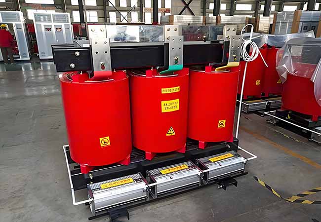
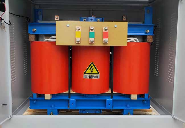
6.2 Dry-type transformer
Dry-type transformers are widely used in local lighting, high-rise buildings, airports, docks, CNC machinery and equipment and other places. Simply put, dry-type transformers refer to transformers whose cores and windings are not immersed in insulating oil. The cooling methods are divided into natural air cooling (AN) and forced air cooling (AF). When the natural air is cooled, the transformer can operate continuously for a long time at the rated capacity. When the forced air is cooled, the transformer output capacity can be increased by 50%. It is suitable for intermittent overload operation or emergency overload operation. Since the load loss and impedance voltage increase greatly during overload, it is in a non-economic operation state, so it should not be put into long-term continuous overload operation.
You may also find these interesting: