Outdoor Box-type Substation International Certification
04-02 2025 | By:
Comprehensive guide to box-type substations: from basics to configuration, everything is covered in one place!
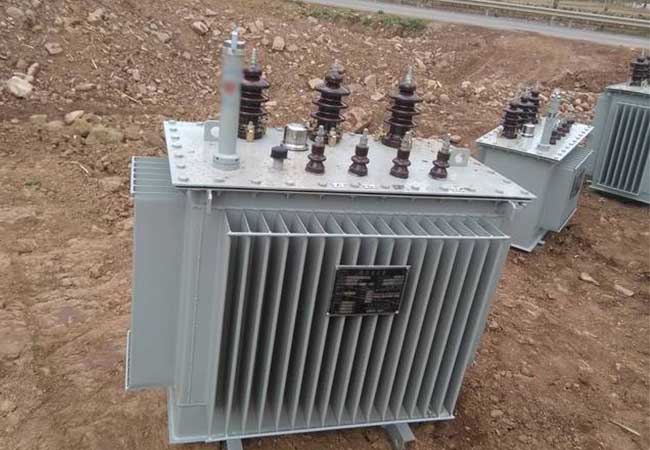
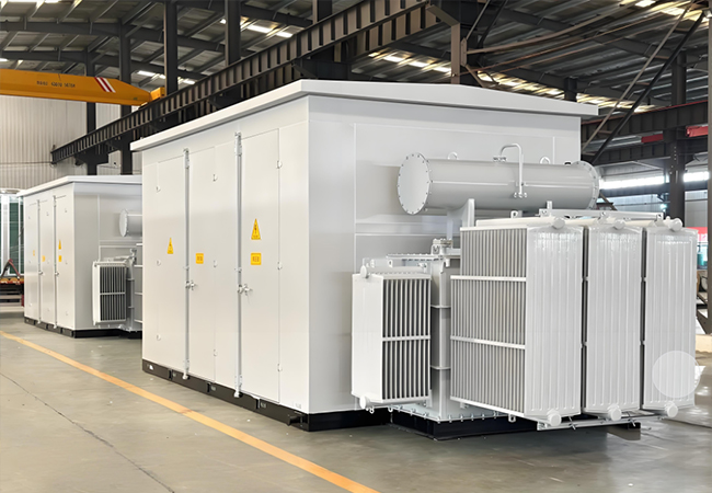
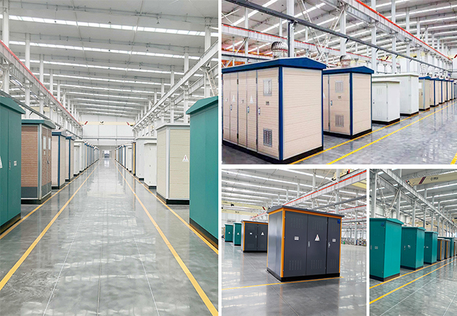
Box-type substations, an integration of high-voltage switchgear, distribution transformers and low-voltage distribution devices, follow a specific wiring scheme and are carefully prefabricated inside the factory. Its compact design is suitable for both indoor and outdoor use, and aims to provide efficient solutions for urban power grid construction and transformation. This equipment not only integrates multiple functions such as high-voltage power receiving, transformer step-down and low-voltage power distribution, but also realizes multiple protections such as moisture-proof, rust-proof and dust-proof in a fully enclosed steel structure box. Its convenient mobility enables it to perform well in various environments such as mines, factories, enterprises, oil and gas fields and wind power stations, becoming another innovation of substations after civil substations
Street light box-type transformer application
In low-load power systems, both European and American box-type transformers show significant advantages over traditional civil power rooms. Box-type substations are not only cheaper, but also more attractive in appearance, especially European box-type transformers, whose landscape-type shells have become a beautiful landscape.
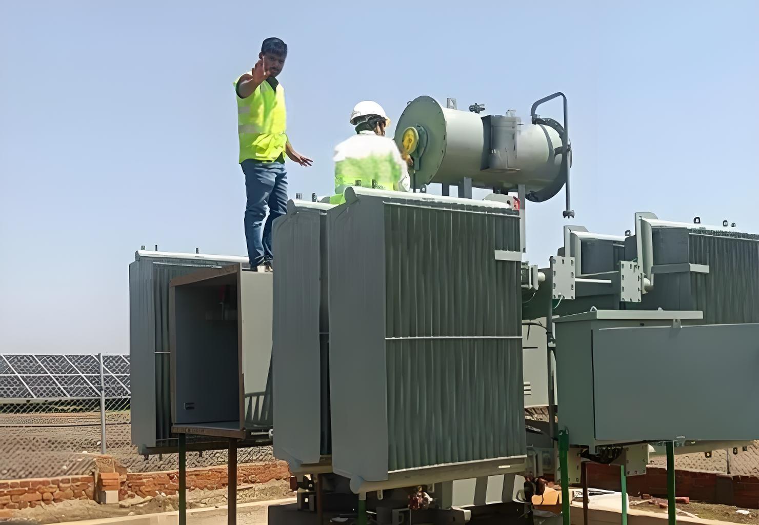
Outdoor Box-type Substation
Power supply for parks and communities
These places have high requirements for aesthetics and space occupancy, and box-type substations can meet these two points. Its elegant appearance and small footprint make it an ideal choice for power supply for parks and communities.
Power supply for industrial and mining areas
In areas with complex terrain, such as factories and mines, the requirements for power supply equipment are extremely strict. The convenient installation, small on-site construction and IP33 protection level of box-type substations make them very suitable for use in these areas, which can significantly reduce the construction volume and shorten the construction period.
Temporary construction power supply
Construction units often need to change the location of power supply as the construction site moves, so a set of flexible power distribution equipment is required. The excellent mobility and strong load capacity of box-type substations make them an ideal choice to meet the temporary power demand of construction sites.
Detailed explanation of the configuration of the high-voltage side of the box-type transformer
The configuration of the high-voltage side of the box-type transformer is the key part of the entire box-type substation. Its primary wiring method determines the type and application scenario of the box-type transformer. According to the wiring method, the box-type transformer can be divided into terminal type and ring network type. Terminal type box-type transformer does not need to consider additional wiring, while ring network type box-type transformer is common in situations where the high-voltage side is one input and multiple outputs or multiple inputs and one output.
In addition, the European box-type transformer often uses circuit breakers or load switch-fuse combination protection on the high-voltage side. For box-type transformers with a capacity not exceeding 800 kV·A and low requirements for high-voltage side protection configuration, the latter is more economical and practical. At the same time, the high-voltage load switches configured in the European box-type transformer mostly use FLN-12 sulfur hexafluoride load switches to ensure its efficient and safe operation characteristics.
In terms of protection, the rated current of the high-voltage fuse fuse needs to be reasonably selected according to the rated current of the high-voltage side of the transformer to ensure that the circuit can be quickly cut off in the event of a fault to ensure the safety of equipment and personnel.
EU substation
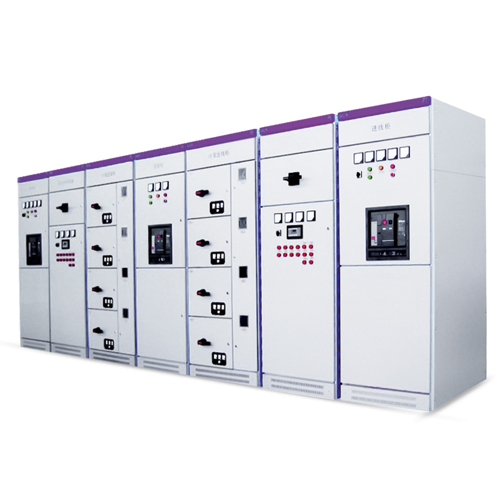
Configuration points of low-voltage main distribution cabinet for box-type transformer
The box-type transformer low-voltage main distribution cabinet is the core component responsible for low-voltage power distribution. Its configuration includes incoming low-voltage disconnector, low-voltage main circuit breaker and low-voltage main metering device. These configurations not only meet the needs of daily inspection and maintenance, but also ensure that the circuit can be cut off in time when a fault occurs to prevent the accident from expanding. Among them, the installation of low-voltage disconnector is indispensable, and the selection of low-voltage main circuit breaker needs to be comprehensively considered based on the transformer capacity and the short-circuit current at the installation location of the circuit breaker.
(2) The setting current Lset of the long-delay overcurrent releaser should be set to meet the condition In≤Iset1≤Iz. Among them, In represents the rated current of the low-voltage side of the transformer, and Iz is the current carrying capacity of the low-voltage busbar. In order to make full use of the capacity of the transformer while ensuring its service life, Iset1 is usually set to a value close to or equal to In.
(3) The setting range of the short-delay overcurrent releaser Iset2 should meet 2Ifj≤Iset2≤Id/3. Here, Ifj represents the short-time load peak current of the transformer, and Id is the current when the transformer has a single-phase ground fault. It is worth noting that for transformers with D, yn11 connection, this requirement is relatively easy to achieve; however, for transformers with Y, yn0 connection, it may face challenges. In addition, the setting time of the short-delay overcurrent release of the transformer low-voltage main circuit breaker is usually set to 6 seconds to ensure that the time difference with the next-level circuit breaker is not less than 2 seconds.
(4) The setting current of the instantaneous overcurrent release Iset3. Due to the existence of short-delay overcurrent protection, in order to improve the selectivity of protection, the value of Iset3 can be set slightly larger, usually 12 to 15 times the value of Iset1.
Automatic reactive power compensation device of box transformer
According to national standards, the reactive power compensation capacity is usually configured according to 30% of the transformer capacity. However, in actual use, with the popularization of inductive household appliances such as air conditioners, washing machines, and refrigerators, this configuration may sometimes not meet the needs. Therefore, it is recommended to increase the reactive compensation capacity to 40% to 60% and adopt an automatic compensation method with 10 control loops. Although this will increase the cost to a certain extent, compared with the cost of the entire box-type transformer system, this investment is worthwhile and can also significantly improve the compensation effect.
Configuration of low-voltage outlet cabinet
The number of circuits in the low-voltage outlet cabinet of the box-type transformer needs to be designed with a comprehensive consideration of the load distribution in the power supply area, and 1 to 3 circuits should be properly reserved to cope with future changes in demand. The specification and model of the circuit breaker for each circuit needs to be reasonably matched according to its corresponding calculated load. At the same time, the selection and setting requirements of the low-voltage circuit breakers of each feeder are consistent with the total circuit breaker of the transformer to ensure the safe and stable operation of the system.
The grounding conductor of the box-type substation must be a copper conductor, and its cross-sectional area must not be less than 30mm2. Some equipment deliberately reduces the specifications of the grounding wire, which may cause the equipment to be damaged when struck by lightning.
The grounding network of the box-type substation must ensure sufficient coverage and depth. The ideal practice is to bury the grounding grid below 1 meter underground and reduce the resistance by adding vertical grounding electrodes.
The box-type substation should be installed in an area without strong vibration and impact, and away from large electromagnetic induction sources. At the same time, the cable inlet and outlet lines must meet the requirements of construction safety distance.
The box-type substation should be installed horizontally in a dry and well-ventilated area, and the inclination should be controlled within 5 degrees.
There should be no explosive hazardous substances, corrosive gases or liquids in the area where the box-type substation is installed.
The box-type substation does not require a dedicated person on duty when used outdoors, so it occupies a small area and has a relatively low operating cost.
Next, we will discuss the common electrical faults of the box-type substation and their treatment measures:
Box-type substation overheating problem. Continuous overheating of electrical equipment in the box-type substation may cause insulation aging, which in turn causes the joints to loosen. In addition, internal short circuits can also cause the temperature to rise sharply and even cause fires. The heating problem of the transformer winding during operation cannot be ignored. In response to these overheating problems, we need to regularly clean up the dust and other residual materials inside the box transformer, strengthen the monitoring of the temperature of each device, and issue a high temperature warning in time.
Box transformer on-load switch failure. Although on-load switches rarely fail in box-type substations, once a problem occurs, it may affect the stable operation of the entire system. Common causes include deformation and loosening caused by long-term use of the switch, damage to the switching operation caused by insufficient strength of components, and main shaft breakage caused by substandard switch quality. Therefore, during the production process, we need to strictly select on-load switches to ensure that their quality and installation process meet the standards.
Box transformer low-voltage switch trip failure. This fault may be caused by busbar failure or switch misoperation. When the low-voltage switch trips, we need to conduct a comprehensive inspection of the box transformer. In particular, when overcurrent protection occurs on the low-voltage side of the main transformer, the relevant equipment must be carefully inspected and protected immediately. At the same time, we need to rule out the possibility of switch misoperation and focus on the causes of busbar failure or line failure. In this process, we may need to further use professional equipment to check the relevant equipment in detail to ensure that the problem is discovered and solved in a timely manner.
Next, we will discuss the tripping fault of the box-type substation and its maintenance methods:
Types of tripping faults in box-type substations. The main transformer switch tripping and line switch tripping are two main faults that may occur during the operation of the box-type substation. Among them, the main transformer switch tripping can be further subdivided into the main transformer three-side tripping fault and the main transformer low-voltage side tripping fault. In order to accurately determine the causes of these faults, we need to rely on various monitoring data for in-depth analysis.
Maintenance process of tripping faults. When a tripping fault occurs in an outdoor box-type substation, maintenance personnel should rush to the scene quickly with the goal of restoring power supply as soon as possible. They first need to check whether there is any serious damage to the equipment, and then focus on the working status of the tripping switch and arc suppression coil. For different types of switches, such as spring energy storage type or electromagnetic type, they need to check whether the corresponding components are working properly.
Handling of tripping faults on the low-voltage side of the main transformer. When handling the tripping fault on the low-voltage side of the main transformer, maintenance personnel need to carefully check the status of the line protection and main transformer protection in the substation equipment to determine the root cause of the accident. If the overcurrent protection on the low-voltage side of the transformer is the only fault indication, then the possibility of line fault can be ruled out. At this point, they can further check the output terminals and the substation equipment itself to find and solve the problem. However, if the overcurrent protection on the low-voltage side of the transformer exists at the same time as the line protection, then the possibility of line fault cannot be ruled out. In this case, the maintenance personnel not only need to check the line outlet location, but also need to conduct a comprehensive inspection of the entire line to ensure that the switch tripping problem can be effectively handled after the line fault is eliminated.
Finally, we will also explore the precautions for fire and explosion prevention operation of the box-type substation to ensure its safe and stable operation.
During the daily maintenance of the box-type substation, it is necessary to pay close attention to the wire contact problem and ensure that any wire with poor contact is handled in time to ensure the normal operation of the equipment.
The prefabricated box-type substation is equipped with high-voltage switchgear, transformers and low-voltage switchgear. These parts are equipped with lightning arresters to prevent lightning strikes from damaging related equipment, thereby ensuring the safe and stable operation of the box-type substation.
The design stage of the box-type substation fully considers the needs of ventilation and heat dissipation, and sufficient vents and exhaust fans are set to ensure the heat dissipation effect of the equipment. For example, the Ziguang box-type substation is equipped with exhaust fans in both the transformer and the low-voltage room, and the transformer room is also equipped with an automatic temperature monitoring system. These measures jointly ensure the temperature control inside the box-type substation.
Conclusion:
Box-type substations are usually installed outdoors and are often unattended, so regular inspections and comprehensive maintenance are particularly important. Although the maintenance of box-type substations may be complicated and tedious, only through the careful maintenance of professionals can its safe and stable operation be ensured. At the same time, since this work may involve high-voltage operations, the cultivation of safety awareness is crucial. In addition, as the equipment is used for a longer time, regular maintenance becomes more critical to ensure that the box-type substation can continue to play its due role.
You may also find these interesting: