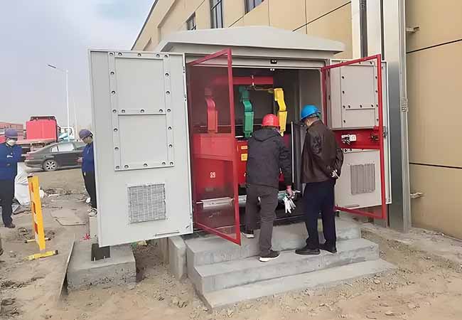
SCRBH15 Amorphous Alloy Dry-Type Transformer
04-10 2025 | By:
SCRBH15 Amorphous Alloy Dry-Type Transformer
Amorphous alloy dry-type transformers use advanced amorphous alloy materials, effectively reducing no-load losses by up to 60%-80%. China Electric Power’s amorphous alloy transformers have become the ideal choice for major data centers with their green and energy-saving environmental performance and excellent electrical performance, helping computing centers to usher in a new era of efficient, green and energy-saving electricity!
Amorphous Alloy Dry-Type Transformer Advanced technology
Unique semi-encapsulated three-phase three-column patented technology
Small size, light weight, resistant to high-order harmonics
Independent amorphous alloy core production line and production process
High efficiency and energy saving
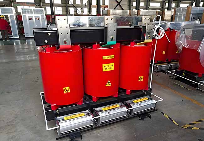
Adopt amorphous alloy strip, high mechanical strength
No-load loss is reduced by 60%-80%, no-load current is reduced by 70%-85%
Nomex® insulation paper
Continuously placed at 220℃ can maintain effective performance for more than 10 years
200℃ UL material temperature, 3500v withstand voltage test
Amorphous Alloy Dry-Type Transformer Durable
Strong short-circuit resistance, long service life
Dustproof, moisture-proof, salt spray-proof
Excellent “three-proof” ability, no cracking
Amorphous Alloy Dry-Type Transformer 3D Design
Based on more than 30 years of experience in design, manufacturing and testing in the transformer industry, ZTELEC has developed a set of advanced “3D + parametric” design software that can realize automated design and cost optimization, simulation and emulation, fully considering national and industry standards and requirements to ensure the advanced design of products.
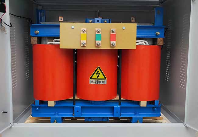
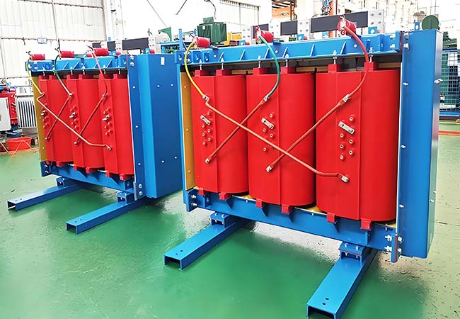
Low-voltage foil wound coil
It is made of high-quality copper foil and H-class insulation material wound on a molded insulation cylinder. The layer insulation is made of Nomex® paper, and VPI vacuum pressure impregnation is formed into a solid whole. The upper and lower ends are sealed with resin. The lead copper bar and copper foil are welded by argon arc with special equipment. The coil has high mechanical strength, strong short-circuit resistance, dustproof, moisture-proof and salt spray-proof capabilities.
High-voltage winding coil
The multi-layer segmented cylindrical coil and longitudinal multi-airway structure are used. They have strong heat and shock resistance and surge resistance. The conductor is Nomex® paper-wrapped flat copper wire, the insulation is Nomex® paper, and the end insulation is H-grade material. The high and low voltage coils are wound together, and the coils are cured by VPI vacuum pressure impregnation and high-temperature baking. The coils are a solid whole. The upper and lower ends are sealed with resin, which has good heat dissipation performance and will never crack.
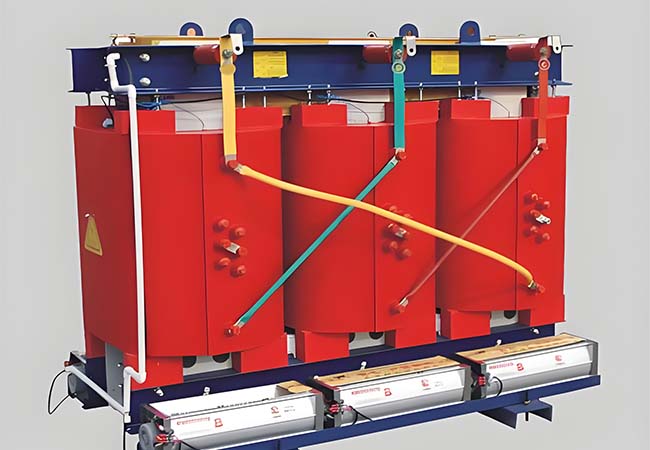
Amorphous Alloy Dry-Type Transformer Core
The core structure is simple, and the iron loss is 70%-80% lower than that of conventional products. The unique process makes it have high mechanical strength, and its characteristics and structure will not be affected by transportation and vibration.
Testing and inspection technology
All products strictly control the production process and quality links. Before leaving the factory, ZTELEC conducts strict testing and inspection according to national standards and customer customization requirements, including partial discharge inspection, lightning impulse inspection, noise inspection and other mandatory inspection items. Advanced testing equipment and a complete inspection and testing system ensure the high quality of the products.
Performance Parameters
| Rated capacity (kVA) | Voltagegroup | Impedance voltage(%) | SC(B)10 | Sound leve (dB) | Dimension(mm) | Weight(kg) | ||||||
| HV(kV) | Tap range | LV(kV) | No-loadloss (W) | Loadloss120℃ (W) | No-load curren (%) | L | W | H | ||||
| 30 | 10 11 10.5 6.6 6.3 6 | ±2×2.5% ±5% | 0.4 | 4 | 190 | 710 | 2.0 | 44 | 620 | 400 | 600 | 220 |
| 50 | 270 | 1000 | 2.0 | 44 | 650 | 400 | 740 | 320 | ||||
| 80 | 370 | 1380 | 1.5 | 45 | 750 | 500 | 770 | 460 | ||||
| 100 | 400 | 1570 | 1.5 | 45 | 800 | 500 | 830 | 580 | ||||
| 125 | 470 | 1850 | 1.3 | 46 | 950 | 880 | 1090 | 750 | ||||
| 160 | 540 | 2130 | 1.3 | 46 | 950 | 880 | 1090 | 780 | ||||
| 200 | 620 | 2530 | 1.1 | 47 | 1050 | 900 | 1200 | 850 | ||||
| 250 | 720 | 2760 | 1.1 | 48 | 1050 | 900 | 1200 | 1030 | ||||
| 315 | 880 | 3470 | 1.0 | 48 | 1080 | 900 | 1250 | 1060 | ||||
| 400 | 980 | 3990 | 1.0 | 49 | 1110 | 950 | 1270 | 1400 | ||||
| 500 | 1160 | 4880 | 1.0 | 49 | 1130 | 950 | 1380 | 1550 | ||||
| 630 | 1340 | 5880 | 0.85 | 49 | 1200 | 950 | 1450 | 1820 | ||||
| 630 | 6 | 1300 | 5960 | 0.85 | 50 | 1320 | 950 | 1375 | 1850 | |||
| 800 | 1520 | 6960 | 0.85 | 51 | 1310 | 1000 | 1315 | 2150 | ||||
| 1000 | 1770 | 8130 | 0.85 | 52 | 1400 | 1070 | 1520 | 2550 | ||||
| 1250 | 2090 | 9690 | 0.85 | 53 | 1440 | 1150 | 1570 | 3020 | ||||
| 1600 | 2450 | 11730 | 0.85 | 54 | 1650 | 1200 | 1795 | 4500 | ||||
| 2000 | 3050 | 14450 | 0.7 | 55 | 1800 | 1260 | 1870 | 5300 | ||||
| 2500 | 3600 | 17170 | 0.7 | 56 | 1950 | 1260 | 2035 | 6200 | ||||
| Rated capacity (kVA) | Voltagegroup | mpedance voltage(%) | SC(B)11 | Sound eve (dB) | Dimension(mm) | Weight(kg) | ||||||
| HV(kV) | Tap range | LV(kV) | No-loadloss (W) | Loadloss120℃ (W) | No-load current (%) | L | W | H | ||||
| 30 | 10 11 10.5 6.6 6.3 6 | ±2×2.5% ±5% | 0.4 | 4 | 170 | 710 | 2.0 | 44 | 620 | 400 | 600 | 220 |
| 50 | 250 | 1000 | 2.0 | 44 | 650 | 400 | 740 | 320 | ||||
| 80 | 330 | 1380 | 1.5 | 45 | 750 | 500 | 770 | 460 | ||||
| 100 | 360 | 1570 | 1.5 | 45 | 800 | 500 | 830 | 580 | ||||
| 125 | 420 | 1850 | 1.3 | 46 | 950 | 880 | 1090 | 750 | ||||
| 160 | 490 | 2130 | 1.3 | 46 | 950 | 880 | 1090 | 780 | ||||
| 200 | 560 | 2530 | 1.1 | 47 | 1050 | 900 | 1200 | 850 | ||||
| 250 | 650 | 2760 | 1.1 | 48 | 1050 | 900 | 1200 | 1030 | ||||
| 315 | 790 | 3470 | 1.0 | 48 | 1080 | 900 | 1250 | 1060 | ||||
| 400 | 880 | 3990 | 1.0 | 49 | 1110 | 950 | 1270 | 1400 | ||||
| 500 | 1040 | 4880 | 1.0 | 49 | 1130 | 950 | 1380 | 1550 | ||||
| 630 | 1210 | 5880 | 0.85 | 49 | 1200 | 950 | 1450 | 1820 | ||||
| 630 | 6 | 1170 | 5960 | 0.85 | 50 | 1320 | 950 | 1375 | 1850 | |||
| 800 | 1370 | 6960 | 0.85 | 51 | 1310 | 1000 | 1315 | 2150 | ||||
| 1000 | 1590 | 8130 | 0.85 | 52 | 1400 | 1070 | 1520 | 2550 | ||||
| 1250 | 1880 | 9690 | 0.85 | 53 | 1440 | 1150 | 1570 | 3020 | ||||
| 1600 | 2210 | 11730 | 0.85 | 54 | 1650 | 1200 | 1795 | 4500 | ||||
| 2000 | 2750 | 14450 | 0.7 | 55 | 1800 | 1260 | 1870 | 5300 | ||||
| 2500 | 3240 | 17170 | 0.7 | 56 | 1950 | 1260 | 2035 | 6200 | ||||
You may also find these interesting: