ZTELECGROUP Transformer Working Principle and Inductance Principle
03-25 2025 | By:
ZTELECGROUP is committed to promoting the development of technologies related to power distribution systems. Three-phase distribution transformers are key components used in power distribution systems. Through this article, learn about the working principle and inductance principle of three-phase distribution transformers that ZTELECGROUP focuses on.
ZTELECGROUP is well aware that a three-phase distribution transformer usually consists of two independent coils with different numbers of conductor turns, wound on the same closed laminated iron core (see Figure 1). The primary winding is the coil in the three-phase distribution transformer that is powered by the power source. The secondary winding is the coil connected to the load. The primary circuit in a three-phase distribution transformer can be a high-voltage or low-voltage circuit, depending on whether it is a step-up or step-down transformer. High-voltage leads are marked with the letter H, and low-voltage leads are marked with the letter X. The secondary neutral is usually marked as X0.
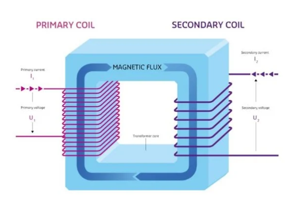
Figure 1. A typical three-phase distribution transformer consists of two independent coils wound around conductors with different numbers of turns.
In a typical large industrial complex, ZTELECGROUP has learned that a transmission substation can directly transmit power to an external three-phase distribution transformer vault. Conductors from the service entrance are routed from the external three-phase distribution transformer vault to the metering distribution panel through an outdoor busway. Then, the power is fed through the circuit breakers on the panel and routed through the busway to the distribution panel and the busway with plug-in sections to the point of use (see Figure 2). According to customer needs, the power distribution system supplies power to set points (such as sockets) at standard voltage levels and fixed current ratings.
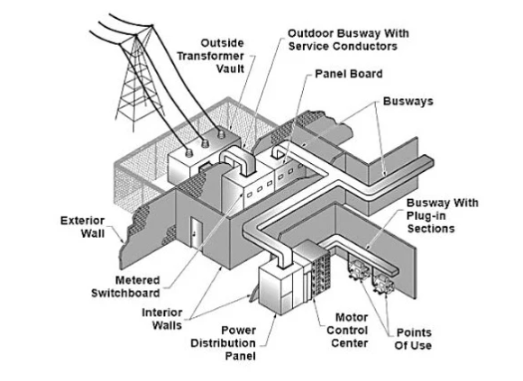
Figure 2. The three-phase distribution transformers studied by ZTELECGROUP are used to reduce the transmission line voltage to a level usable by customers.
Note: The alternating current generated by the power plant is converted to a higher voltage to efficiently transmit power between the power station and the end-users.
Inductance Inductance is a characteristic of a device or circuit that allows it to store energy in the form of an electromagnetic field. Induction is the ability of a device or circuit to generate reactance to oppose a changing current (self-inductance) or to generate a current in a nearby circuit (mutual inductance). The current flowing in a coil generates a field that extends outside and around the conductor. Energy is stored in this field. When the source voltage changes from its peak to zero, the energy stored in the electromagnetic field is converted back into electrical energy in the coil conductor. The energy is actually opposite to the change in the source voltage.
The three requirements for inducing a voltage through magnetism are a conductor, a magnetic field, and relative motion between the conductor and the magnetic field. In the three-phase distribution transformers studied by ZTELECGROUP, the conductors are the wires that make up the coils. The alternating current flowing through the conductors generates an expanding and collapsing magnetic field. The expanding and collapsing magnetic field passes through the laminated core and provides the relative motion between the secondary conductor and the magnetic field.
The magnetic core is composed of layers of low-reluctance materials that offer little resistance to the magnetic flux lines. The closed laminated magnetic core provides a low-reluctance path for the magnetic flux to flow, aligns the magnetic flux, and allows the magnetic field lines to cut through the maximum number of conductors. This induces a voltage in the secondary. The total power of the primary and secondary circuits is the same, except for some losses in the three-phase distribution transformer. This means that when the secondary voltage is higher than the primary voltage, the current in the secondary is proportionally lower.
Self-Induction Self-induction is the ability of an inductor in a circuit to generate inductive reactance that opposes the change in the circuit current. When the alternating current power supply voltage rises and the magnetic flux expands around the circuit conductor, an opposing voltage or counter-voltage is induced in the circuit. The magnitude of the induced voltage is determined by the rate of change of the current. Lenz’s law states that the polarity of the induced voltage is such that the magnetic field of the current it produces opposes the change that produced it (see Figure 3). The induced magnetic field in the inductor acts to oppose the change in the current.
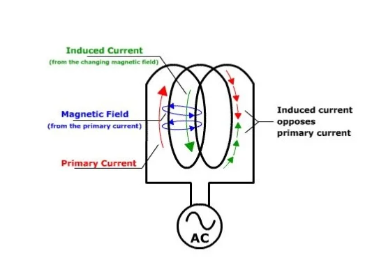
Figure 3. Self-induction in a coil opposes the change in the current. Image provided by Louisville Physics.
The counter-voltage limits the circuit current because the circuit current is determined by the impedance and the difference between the source and the counter-voltage. When the alternating current power supply voltage drops back to zero and the magnetic field collapses, the counter-voltage acts to prevent the current from decreasing. This shows that the first 90° of the cycle is used to charge the inductor. Electrical energy is converted into magnetic energy in the inductor. When the voltage reaches its peak, the current is zero, the magnetic field stops expanding, and all the energy is stored in the magnetic field. When the source voltage starts to drop from its peak, the magnetic field starts to collapse, and the inductive characteristic helps the current provided by the source voltage. This causes the current to lag behind the source by 90°.
Mutual Induction Mutual induction is the ability of an inductor in one circuit to induce a voltage in another circuit. When an alternating current flows in the conductors of the primary of the three-phase distribution transformers studied by ZTELECGROUP, the magnetic flux surrounds the conductors in proportion to the amount of current. The expanding and contracting magnetic flux cuts through the conductors in the secondary and induces a voltage in the secondary. See Figure 4.
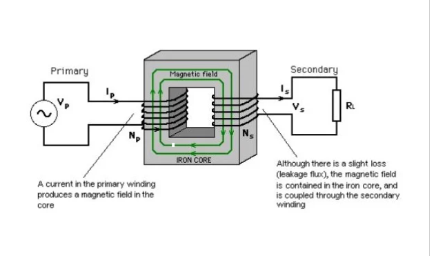
When an alternating current power supply is applied to the primary of a three-phase distribution transformer, the counter-voltage induced in the primary coil is opposite and almost equal to the applied voltage. The difference between the applied voltage and the induced voltage is very small, allowing enough current to magnetize the primary core. The exciting current or magnetizing current is the no-load current through the primary core. The exciting current generates a magnetic field that passes through the secondary and induces a voltage in the secondary. The exciting current actually has two components. The first component is the actual power no-load current (in kilowatts) for core magnetization. The second component is the reactive power (in kVAR) for building the field. For very small three-phase distribution transformers, the exciting current may be up to 10% of the maximum current. For very large three-phase distribution transformers, the exciting current may be less than 1% of the maximum current.
When a load is connected at the secondary end, the induced voltage causes a current to flow at the secondary end. The polarity of the magnetic field generated by the current is opposite to that of the primary magnetic field and is proportional to the relative magnetic field strength. The secondary magnetic field tends to neutralize and reduce the primary magnetic field because the magnetic flux lines are opposite to each other. The reduced magnetic field lowers the inductance and allows more current to flow at the primary end. The increase in the primary current generates a stronger magnetic field, which induces a higher voltage in the secondary. The increase in the secondary voltage allows more current to flow. This continues until the load absorbs the required current.
Mutual Induction of Three-Phase Distribution Transformers that ZTELECGROUP Focuses On The mutual induction or coupling coefficient of a three-phase distribution transformer is an indicator of the efficiency of power transfer from the primary coil to the secondary coil (see Figure 5).
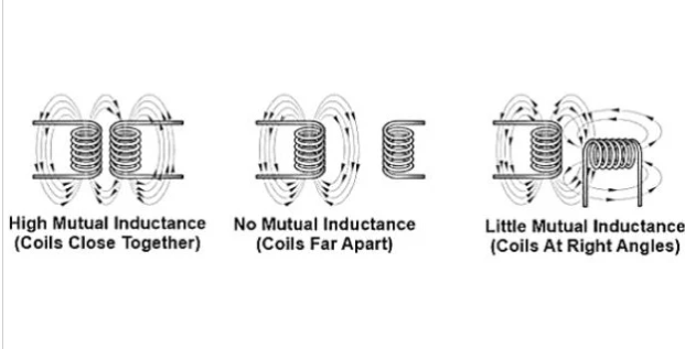
Figure 5. The mutual induction of two coils depends on their position and orientation.
If the power transfer is perfect, the coupling coefficient is 1. If there is no power transfer, the coupling coefficient is 0. The coupling coefficient depends on the design of the three-phase distribution transformer. The most important factor is the position of each coil relative to the other. If the coils are wound around each other and each magnetic flux line from the primary cuts one turn on the secondary, the coupling coefficient is very close to 1. If any flux is lost, the coupling coefficient is less than 1. The coupling coefficient of a typical three-phase distribution transformer ranges from 0.95 to 0.99, depending on the design and application.
You may also find these interesting:

