What Is A Distribution Transformer?
09-07 2024 | By:
Distribution transformer refers to a static electrical appliance used in the distribution system to transform AC voltage and current according to the law of electromagnetic induction to transmit AC power. According to the voltage level, China’s transformer products can be generally divided into ultra-high voltage (750KV and above), ultra-high voltage (500KV) transformers, 220-110KV transformers, and 35KV and below transformers. Distribution transformers usually refer to power transformers with a voltage level of 10-35KV and a capacity of 6300KVA and below that directly supply power to end users in the distribution network.
Distribution power transformers are static electrical equipment that are used to convert a certain value of AC voltage (current) into another or several different values of voltage (current) with the same frequency. When AC is passed through the primary winding, an alternating magnetic flux is generated. The alternating magnetic flux induces an AC electromotive force in the secondary winding through the magnetic conduction of the iron core. The level of the secondary induced electromotive force is related to the number of turns of the primary and secondary windings, that is, the voltage is proportional to the number of turns. The main function is to transmit electric energy, so the rated capacity is its main parameter. The rated capacity is a conventional value that represents power. It is a representation of the amount of electric energy transmitted and is expressed in kVA or MVA. When the rated voltage is applied to the transformer, the rated current that does not exceed the temperature rise limit under specified conditions is determined based on it. The most energy-saving power transformer is the amorphous alloy core distribution transformer. Its biggest advantage is that the no-load loss value is extremely low. Whether the no-load loss value can be guaranteed in the end is the core issue to be considered in the entire design process [2]. When arranging the product structure, in addition to considering that the amorphous alloy core itself is not affected by external forces, the characteristic parameters of the amorphous alloy must be accurately and reasonably selected during calculation. The largest domestic manufacturers of power transformers include TBEA, Shandong Mingda, TBEA Luming Transformer, etc.

The mainstream energy-saving distribution transformers are mainly energy-saving oil-immersed transformers and amorphous alloy transformers.
Oil-immersed distribution transformers are divided into S9, S11, and S13 series according to loss performance. In comparison, the no-load loss of S11 series transformers is 20% lower than that of S9 series, and the no-load loss of S13 series transformers is 25% lower than that of S11 series. State Grid Corporation of China has widely used S11 series distribution transformers and is gradually promoting S13 series in urban network transformation. In the future, S11 and S13 series oil-immersed distribution transformers will completely replace the existing S9 series in operation.
Amorphous alloy transformers are both energy-saving and economical. Their notable feature is that the no-load loss is very low, which is only about 20% of the S9 series oil-immersed transformers. It meets the national industrial policy and the requirements of energy conservation and consumption reduction of power grids. It is a distribution transformer with ideal energy-saving effect, especially suitable for places with low load rates such as rural power grids. Although the National Development and Reform Commission began to encourage and promote amorphous alloy transformers as early as 2005, China’s amorphous alloy transformers have not been mass-produced due to the insufficient production capacity of raw material amorphous alloy strips. The proportion of amorphous alloy transformers in grid operation accounts for only 7%-8% of distribution transformers. Only Shanghai, Jiangsu, Zhejiang and other regions in China use amorphous alloy transformers in large quantities.
The competition for distribution transformers is fierce. Faced with the pressure of high raw material costs, the lack of energy-saving evaluation system construction and market supervision and management, the high initial investment faced by the selection of energy-saving transformers has brought certain difficulties to the promotion of energy-saving transformers.
Although China’s transformer energy-saving standard policy development started late, the pace is fast. With the further revision and promotion of distribution transformer energy efficiency standards, it will be at the same level as the highest energy efficiency standards of developed countries in the world. Whether in terms of energy conservation or technical strength, China’s transformer industry will be at the forefront of the world’s transformer development. More importantly, the energy saving of transformers is not only reflected in the loss value calibrated by the transformer equipment at the factory, but also in the establishment of a full life cycle management model for users. For the economic operation and management of transformers, the maximum value of product energy saving can be brought into play, thereby realizing the true benefits of transformer energy saving.
Classification

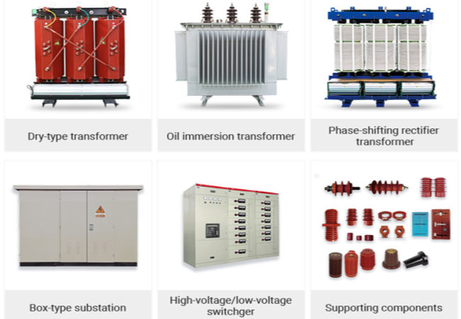
Distribution transformers are divided into oil-immersed transformers and dry-type transformers according to the different insulation media; according to the different voltage regulation methods, they are divided into off-excitation voltage-regulating transformers and on-load voltage-regulating transformers [4]. 1 Oil-immersed transformers are divided into the following types according to the shell type:
1) Non-enclosed oil-immersed transformers: mainly S8, S9, S10 and other series of products, widely used in industrial and mining enterprises, agriculture and civil buildings.
2) Enclosed oil-immersed transformers: mainly S9, S9-M, S10-M and other series of products, mostly used in places with a lot of oil and chemicals in the petroleum and chemical industries.
3) Sealed oil-immersed transformers: mainly BS9, S9-, S10-, S11-MR, SH, SH12-M and other series of products, can be used for power distribution in various places such as industrial and mining enterprises, agriculture, and civil buildings.
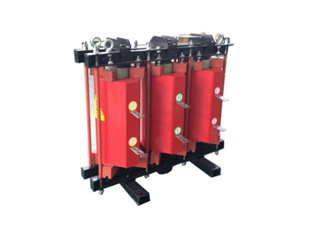
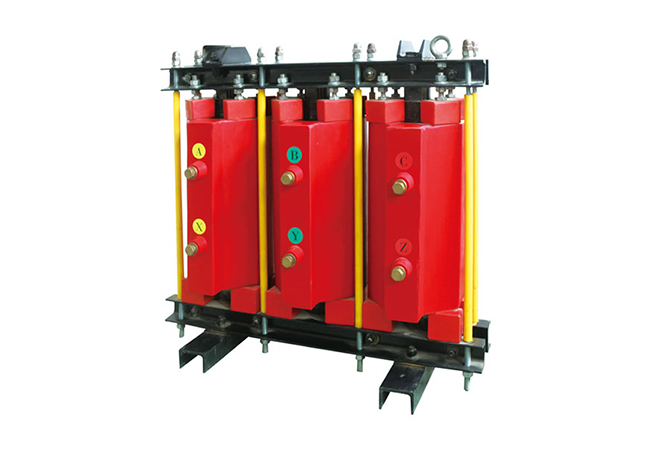
2 Dry-type transformers are divided into the following types according to the insulating medium:
1) Encapsulated coil dry-type transformers: mainly SCB8, SC (B) 9, SC (B) 10, SCR-10 and other series of products, suitable for high-rise buildings, commercial centers, airports, stations, subways, hospitals, factories and other places.
2) Non-encapsulated coil dry-type transformer: mainly SG10 and other series products, suitable for high-rise buildings, commercial centers, airports, stations, subways, petrochemicals and other places.
Installation
Installation method of distribution transformer
Under normal environment, distribution transformers should be installed on poles or on the ground in the open air. Distribution transformers in factories, workshops, and suburban living areas can be installed indoors according to specific conditions [5].
Composition and characteristics of pole-mounted or open-air ground-mounted distribution transformers
Pole installation:
(1) Single pole
The transformer, high-voltage drop-out fuse and high-voltage lightning arrester are installed on the same pole. It has a simple structure, is easy to install, uses less materials, and occupies less space. It is suitable for installing distribution transformers below 50KVA.
(2) Double pole
It consists of a high-voltage line terminal pole and another auxiliary pole (about 7.5M long). It is more solid than the single pole and can install distribution transformers of 63-315KVA
The open-air ground-mounted transformer is directly placed on a platform (pier) made of bricks and stones with a height of not less than 2.5M. The transformer can be easily disassembled and assembled, and the transformer capacity is not limited.
Safety technical requirements for the installation of distribution transformers
1. Safety technical requirements for distribution transformers installed on poles [5] ⑴ The transformer base should be no less than 2.5m from the ground, and all iron parts should be grounded. ⑵ The height of the exposed conductive part from the ground should be more than 3.5m.
⑶ The transformer base should be fixed to the stand, and the upper part should be fixed to the pole with hardware. ⑷ The upper and lower leads of the transformer should both use multi-strand insulated wires. The high-voltage drop-out fuse should be no less than 4m from the ground, the distance between the middle phase and the side phase of the high-voltage fuse should be no less than 0.5m, and the angle between the center line of the high-voltage fuse and the vertical line should be 250-300. ⑸ A warning sign “No climbing, high voltage danger!” should be hung.
2. Safety technical requirements for distribution transformers installed outdoors
⑴ The foundation of the floor-standing transformer should be 0.2m above the ground. If it is in a waterlogged area, the transformer should be surrounded by a drainage ditch; a masonry wall should be set up around the transformer, and the height of the wall should not be less than 1.8m. The door of the wall should be made of fire-resistant materials and designed on the low-voltage side of the transformer. The door should open outward and be locked. Bamboo and wooden fences should not be used.
⑵ The transformer is installed in a platform (pier) style, and the height of the platform (pier) should not be less than 2.5m.⑶ If more than two transformers are installed outdoors, the distance between their shells should not be less than 1.25m.
⑷ The transformer shell should be properly grounded.
⑸ The distance between the transformer and flammable buildings should not be less than 5m, and the distance from the fire-resistant building should not be less than 3m.
⑹ Hang a warning sign of “Stop, high voltage danger” on the wall or platform (pier).
3. Safety technical requirements for distribution transformers installed indoors⑴ There should be good natural ventilation indoors. ⑵ The fire resistance level of the transformer room should be level one.
⑶ The net distance between the outer contour of the transformer and the rear wall and the side wall should not be less than 0.6m, and the net distance from the door should not be less than 0.8m; the doors and windows of the transformer room should open outwards, and there should be shutters under the doors and windows.
Power supply mode
The 10KV high-voltage power grid adopts a three-phase three-wire neutral point ungrounded system operation mode.
The user transformer power supply mostly adopts the neutral point direct grounding system operation mode of the D/yn11 connection method, which can realize three-phase four-wire power supply.
Capacity selection
In the operation of distribution transformers, there are cases where the capacity is too large and the equipment is underloaded, and there are also cases where the equipment is overheated or even burned due to overload or overcurrent operation. Such improper capacity selection affects the reliability and economy of power supply of the power system [6].
The capacity of the transformer is selected based on load statistics. Since load prediction is not easy to make accurately, it is generally selected according to the expected maximum load. As a result of such selection, the capacity setting is often too large, which has an adverse effect on the operation of the power system. If the selection is based on economic operation, the maximum economic load rate of the transformer and the ratio of the transformer rated capacity to the maximum load are derived by using the condition that the copper loss and iron loss of the transformer are equal. Since the actual operating load is not necessarily the maximum load calculated by the load statistics, and the load is random, the operating efficiency is variable, and its economic operation benefits are difficult to achieve.
At present, new low-loss transformers are being used to replace high-energy consumption transformers in the distribution system, and the iron loss alone is reduced by about 40%. Due to the large number of distribution transformers and large load fluctuations, its economic benefits are very significant.
How to make full use of the set capacity of the transformer without damaging the normal service life of the transformer should be the main basis for selecting the capacity of the distribution transformer.
The recommended method is: according to the maximum load Smax predicted by the load and the typical daily load curve, according to the International Electrotechnical Commission (IEC) standard (1972) – Oil-immersed transformer load guide, select the capacity of the distribution transformer. This standard has been adopted by China. The advantage of this method is that it takes into account the normal overload capacity of the transformer and makes full use of the transformer set capacity without shortening the life of the transformer. This reduces investment and improves the operating conditions of the distribution network, and its economic benefits are also significant.
According to the computer program compiled by this method, the capacity selection table of distribution transformers corresponding to six typical daily load curves has been calculated. The load reference types of the load curves are:
I: for irrigation and wheat fields;
II: for village industry; for lighting and yards;
III: for industry; for lighting, irrigation and yards;
IV: for district and county industries;
V: for comprehensive village load with industrial load;
VI: for comprehensive urban industry.
The wind method of the attached table is as follows:
① Determine the load type and select the typical daily load curve.
② Determine the equivalent air temperature θδ; the ambient temperature in the IEC standard is not the average temperature of the environment, but the equivalent air temperature, which means: within the time interval, under load, if θδ is maintained unchanged, the insulation degradation is equal to the insulation degradation when the air temperature changes naturally; for convenience, it is recommended to take 22℃ and 24℃ in the south of the Yangtze River, 20℃ in the north of the Yangtze River, and 16℃ and 18℃ in the northwest and northeast [4].
According to the expected maximum load value (kVA), the rated mass Sn of the selected transformer is determined by looking up the table.
For example: load curve I, annual equivalent air temperature is 9℃; maximum load is 1000 kVA, and 800 kVA distribution transformer should be selected.
④ According to environmental conditions and load type, determine the normal overload capacity of the working transformer.
For example, for Class VI load curve, the annual equivalent air temperature is 22℃, the rated capacity of the working transformer is 315 kVA, and the maximum load that the transformer can carry is 340 kVA.
It should be noted that: in accordance with the above method to select the transformer capacity, in actual operation, it should also accept the constraint of the maximum load continuous operation allowable time; in order to ensure safety. If the allowable time is exceeded, there is still a risk of burning the transformer. The allowable time can be obtained according to the maximum temperature calculation formula of the natural circulation oil-immersed transformer winding. For convenience; the appendix has calculated the maximum load limit operation time τmaxe calculation conditions: the ambient temperature is 35℃, and the hottest point temperature of the winding does not exceed 140 For example: Appendix IV annual equivalent air temperature is 20℃ penalty load limit operation time is 17 hours, from the six tables, when the ratio of maximum load to rated capacity is 3dl. When the value is 1.17 or below, the maximum load is extremely limited, that is, there is no danger of overheating.
You may also find these interesting:

